API 7CW-2020 pdf download Casing Wear Tests
3.1.4
coefficient of friction
Dimensionless ratio of the friction force between two bodies to the normal force pressing these bodies together.
3.1.5
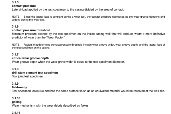
contact pressure
Lateral-load applied by the test specimen to the casing divided by the area of contact.
NOTE Since the lateral-load is constant during a wear test, the contact pressure decreases as the wear groove deepens and widens during the wear test.
3.1.6
contact pressure threshold
Minimum pressure exerted by the test specimen on the inside casing wall that will produce wear; a more definitive predictor of wear than the “Wear Factor”.
NOTE Factors that determine contact pressure threshold include wear groove width, wear groove depth, and the lateral-load of the test specimen on the casing.
3.1.7
critical wear groove depth
Wear groove depth when the wear grove width is equal to the test specimen diameter.
3.1.8
drill stem element test specimen
Tool joint test specimen.
3.1.9
field-ready
Test specimen looks like and has the same surface finish as an equivalent material would be received at the well site.
3.1.10
galling
Wear mechanism with the wear debris described as flakes.
3.1.11
grinding
Wear mechanism with the wear debris described as a powder.
3.1.12
lateral-load (side-load)
Contact force of the test specimen against the casing specimen divided by the net length of the hardband or material coating on the test specimen.
3.1.13
machining
Wear mechanism with the wear debris described as chips.
3.1.14
manufacturer
Principal agent in the design, fabrication, and furnishing of the test specimen who chooses to comply with this standard.
3.1.15
moment-load
Force imparted on casing specimen upon introduction of lateral-load and rotation of the tool joint specimen.
3.1.16
normalized
Test specimens with hardband material come from the manufacturer with varying OD dimensions.
NOTE Normalization is the mathematical process to equate those varying dimensions to 6.25 in. test specimen OD, 9 5 / 8 in.,
58.4 lb/ft casing with 0.595 in. wall.
3.1.17
polishing
Wear mechanism with the wear debris described as a fine powder.
3.1.18
rotational friction factor
Ratio of frictional force and contact force between the test specimen and the casing while rotating.
3.1.19
side-load (lateral-load)
Contact force of the test specimen against the casing specimen divided by the net length of the hardband or material coating on the test specimen.
3.1.20
sliding distance
Distance traveled by a point on the periphery of the test specimen as it contacts the inner casing wall.
3.1.21
specific energy
Energy required to remove one cubic inch of material from one foot of the inner casing wall, lb f -in. per cubic in.
3.1.22
surface finish
Final manufactured or machined exterior evaluated by a mean roughness index number, R a .
3.1.23
surface roughness
Geometrical characteristics of the surface that may include macro-deviations, surface waviness, and microirregularities.
3.1.24
surface roughness number (R a )
Represents the average departure of the surface from perfection measured along a line, running at a right angle to the general direction of tool marks on the surface.
NOTE Typically expressed in units of height; micro-inches (US customary units), microns (metric units), or N scale (ISO 1302:2002). In U.S. customary units, 1 R a is typically expressed in “millionths” of an inch.
API 7CW-2020 pdf download

